Baseline calculation theory


Overall process

The table below describes the overall process of a baseline calculation.

Stage

Description

1

The baseline segments are defined.

2

The baseline points are selected.

3

The baseline is drawn.


Baseline segment definition

Baseline parameters are used to find the baseline segments. The default values for the parameters are determined from the source curve. The baseline segments are found by different parameters that are based on the type of algorithm that is selected.

Note: The parameters can be displayed in the Evaluation module if you choose Integrate:Calculate baseline function. You can also click the Baseline settings button in the Integrate:Peak integrate dialog box.


Morphological algorithm

The Morphological algorithm searches for all parts of the source curve where:

  • The curve parts come into contact at both ends of a horizontal line of the length defined in the Structure width parameter. The default value of this parameter is based on the widest detected peak in the curve. The horizontal line is moved along the curve up the peak until it reaches the contact points. The curve parts below the horizontal line and the line will now form a "curve" with a plateau. The center point in the plateau formed by the horizontal line will be the data point for the baseline.

  • The data points fulfil the Minimum distance between data points. This parameter reduces the total number of data points that are created from a curve.


Classic algorithm

The Classic algorithm searches for all parts of the source curve where:

  • The curve parts are longer than the Shortest baseline segment. This parameter determines the minimum length for a part of the source curve to be considered a possible baseline segment.

  • The curve has no point outside the Noise window. The noise window is defined as a rectangular corridor parallel to the slope of the curve and centered on the first and last points within the currently inspected segment.

  • The slope is less than the Slope limit. This limits the maximum slope of the baseline to differentiate baseline segments from peaks.

  • The curve parts are lower than the Max baseline level. This parameter determines the highest acceptable signal level for the baseline.


Baseline parameters

The baseline parameters can be illustrated as a rectangular box that the source curve has to fit into in order to be identified as a baseline segment, where:

  • The length of the box corresponds to the Shortest baseline segment.

  • The height of the box corresponds to the maximum level of noise on the baseline segments. This is referred to as the Noise window.

  • The box is allowed to be tilted with a maximum slope corresponding to the Slope limit.

  • The box is not allowed to move up above the Max baseline level.


Baseline parameters - illustration

The illustrations below shows the baseline parameters graphically.


Baseline segment identification

The table below describes the baseline segment identification process:

Stage

Description

1

The box is virtually moved along the source curve in steps of one third of the Shortest baseline segment length to look for baseline segments.

2

A baseline segment is found whenever the currently examined part of the source curve fits completely within the box.

3

The found baseline segments are joined by connecting adjacent segments, provided that the slope of the joining lines does not exceed the Slope limit.


Baseline points (Classic algorithm)

When the baseline segments have been defined and joined, they are replaced by baseline points at the start and end of each segment. The line between these is also filled with points.

Note: The baseline points are shown as green squares in the Integrate:Edit baseline function of the Evaluation module.


Baseline drawing

The baseline points are used to create the baseline curve using a spline interpolation. The spline function ensures that the baseline curve is guided by the baseline points. However, the curve does not necessarily pass through the baseline points. The baseline will be a smoothly curved function passing close to or through the points.

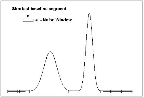
To reduce the effect of noise at the peak integration, the created baseline is forced equal to the source curve in every position where the difference between the baseline and the source curve is small enough. Choose Integrate:Calculate 
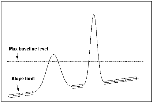
Baseline. If the Accept negative peaks option is off, the baseline will be forced down to the level of the source curve whenever the created baseline goes above the source curve.


How to measure the baseline segment (Classic algorithm)

You can try to measure the Shortest baseline segment length directly on your chromatogram. The table below describes how to do this:

Step

Action

1

Locate the shortest segment of the curve that you consider a part of the baseline.

2

Use the marker box on the chromatogram to measure the length of the segment.

3

Choose Integrate:Calculate Baseline and insert this value as the Shortest baseline segment value.


How to measure noise level (Classic algorithm)

Curve coordinates can also be used to measure noise levels on the source curve. The table below describes how to do this:

Step

Action

1

Use the Zoom function to focus on a part of the curve that is representative for the baseline noise.

2

Select an appropriate Y-axis scale.

3

Measure the Y-axis coordinates.

4

  • Calculate the noise range as the difference between the max. and min. values.

  • Add an extra 20%.

  • Choose Integrate:Calculate Baseline and insert this value as the Noise window value.


How to measure the slope limit (Classic algorithm)

The table below describes how to measure the slope at any part of the curve.

Stage

Description

1

Select Operations:Differentiate in the Evaluation module.

Result: The Differentiate dialog box opens.

2

  • Select the desired source curve.

  • Select the First order calculation option.

  • Click OK.

Result: The differentiated curve will appear in the active chromatogram.

3

Select an appropriate Y-axis scale, right-click and select Marker to measure the Y-axis values for the differentiated curve with the curve coordinates function.

Result: The Y-axis value is interpreted as the UV curve slope at the selected retention point.

4

  • Determine the highest slope value of the baseline (non-peak) part of the curve.

  • Add 10%.

  • Select Integrate:Calculate Baseline and use this value as the Slope limit.

Note: If the differentiated curve is very noisy, it can be filtered with a light Moving average filter in the Operations:Smooth function.


2005-06-15